m (Use textstyle parameter to fmbox) Tag: Possible HTML |
m (Change cat) Tags: Visual edit Possible HTML |
||
| Line 18: | Line 18: | ||
<pre>Bits 0-5: Select the register sub-group |
<pre>Bits 0-5: Select the register sub-group |
||
Bits 6-7: Select the register group. Two groups are currently available: |
Bits 6-7: Select the register group. Two groups are currently available: |
||
| − | |||
00 - palette group |
00 - palette group |
||
| − | |||
When this group is selected, the sub-group determines the |
When this group is selected, the sub-group determines the |
||
entry in the palette table (0-63). |
entry in the palette table (0-63). |
||
| − | |||
01 - mode group |
01 - mode group |
||
| − | |||
The sub-group must be zero. Sub-group entries 1-63 are |
The sub-group must be zero. Sub-group entries 1-63 are |
||
reserved for mode specific controls.</pre> |
reserved for mode specific controls.</pre> |
||
| Line 71: | Line 67: | ||
The complete index can be calculated as |
The complete index can be calculated as |
||
| − | + | <nowiki> </nowiki>ink_colour = (FLASH * 2 + BRIGHT) * 16 + INK |
|
| − | + | <nowiki> </nowiki>paper_colour = (FLASH * 2 + BRIGHT) * 16 + PAPER + 8 |
|
When scaling 3-bits of colour data to 8-bits for emulators that operate in high colour mode the following conversion should be used: |
When scaling 3-bits of colour data to 8-bits for emulators that operate in high colour mode the following conversion should be used: |
||
| − | + | <nowiki> </nowiki>76543210 |
|
| − | + | hmlhmlml |
|
where h is the high bit, m is the middle bit, and l is the low bit of the original 3-bit value. |
where h is the high bit, m is the middle bit, and l is the low bit of the original 3-bit value. |
||
| Line 84: | Line 80: | ||
==== ZXSTPALETTE ==== |
==== ZXSTPALETTE ==== |
||
The state of the ULA registers found in the 64 colour replacement ULA. This block may be present for any machine. |
The state of the ULA registers found in the 64 colour replacement ULA. This block may be present for any machine. |
||
| − | + | <nowiki> </nowiki>// Palette Block flags |
|
| − | + | <nowiki> </nowiki>#define ZXSTPALETTE_DISABLED 0 |
|
#define ZXSTPALETTE_ENABLED 1 |
#define ZXSTPALETTE_ENABLED 1 |
||
| − | + | // Palette Block. Contains the palette register values |
|
| − | + | <nowiki> </nowiki>typedef struct _tagZXSTPALETTEBLOCK |
|
| + | <nowiki> </nowiki>{ |
||
| − | { |
||
ZXSTBLOCK blk; |
ZXSTBLOCK blk; |
||
BYTE chFlags; |
BYTE chFlags; |
||
| Line 100: | Line 96: | ||
'''blk'''<br /> The block header. The block id is ZXSTBID_PALETTE ('P', 'L', 'T', 'T').<br /> '''chFlags'''<br /> A flags that indicates if the palette is enabled or if the normal display mode is in use. This can be one of: |
'''blk'''<br /> The block header. The block id is ZXSTBID_PALETTE ('P', 'L', 'T', 'T').<br /> '''chFlags'''<br /> A flags that indicates if the palette is enabled or if the normal display mode is in use. This can be one of: |
||
| − | {| |
+ | {| border="1" cellpadding="1" cellspacing="1" width="100%" |
| + | |||
| + | |||
|'''Flag''' |
|'''Flag''' |
||
|'''Meaning''' |
|'''Meaning''' |
||
| Line 129: | Line 127: | ||
The palette format doubles as the BASIC patch loader. This enables you to edit patches produced by other people. |
The palette format doubles as the BASIC patch loader. This enables you to edit patches produced by other people. |
||
| ⚫ | |||
| − | <pre> |
||
| ⚫ | |||
; copyright (c) 2009 Andrew Owen |
; copyright (c) 2009 Andrew Owen |
||
; |
; |
||
; The palette file is stored as a BASIC program with embedded machine code |
; The palette file is stored as a BASIC program with embedded machine code |
||
| − | |||
header: |
header: |
||
| − | |||
db 0x00 ; program file |
db 0x00 ; program file |
||
db 0x14, 0x01, "64colour" ; file name |
db 0x14, 0x01, "64colour" ; file name |
||
| Line 142: | Line 137: | ||
dw 0x0000 ; autostart line |
dw 0x0000 ; autostart line |
||
dw 0x0097 ; program length |
dw 0x0097 ; program length |
||
| − | |||
basic: |
basic: |
||
| − | |||
; 0 RANDOMIZE USR ((PEEK VAL "2 |
; 0 RANDOMIZE USR ((PEEK VAL "2 |
||
; 3635"+VAL "256"*PEEK VAL "23636" |
; 3635"+VAL "256"*PEEK VAL "23636" |
||
; )+VAL "48"): LOAD "": REM |
; )+VAL "48"): LOAD "": REM |
||
| − | |||
db 0x00, 0x00, 0x93, 0x00, 0xf9, 0xc0, 0x28, 0x28 |
db 0x00, 0x00, 0x93, 0x00, 0xf9, 0xc0, 0x28, 0x28 |
||
db 0xbe, 0xb0, 0x22, 0x32, 0x33, 0x36, 0x33, 0x35 |
db 0xbe, 0xb0, 0x22, 0x32, 0x33, 0x36, 0x33, 0x35 |
||
| Line 155: | Line 147: | ||
db 0x36, 0x22, 0x29, 0x2b, 0xb0, 0x22, 0x34, 0x38 |
db 0x36, 0x22, 0x29, 0x2b, 0xb0, 0x22, 0x34, 0x38 |
||
db 0x22, 0x29, 0x3a, 0xef, 0x22, 0x22, 0x3a, 0xea |
db 0x22, 0x29, 0x3a, 0xef, 0x22, 0x22, 0x3a, 0xea |
||
| − | |||
start: |
start: |
||
| − | |||
di ; disable interrupts |
di ; disable interrupts |
||
ld hl, 38 ; HL = length of code |
ld hl, 38 ; HL = length of code |
||
| Line 168: | Line 158: | ||
out (c), a ; turn palette mode on |
out (c), a ; turn palette mode on |
||
xor a ; first register |
xor a ; first register |
||
| − | |||
setreg: |
setreg: |
||
| − | |||
ld b, 0xbf ; choose register port |
ld b, 0xbf ; choose register port |
||
out (c), a ; select register |
out (c), a ; select register |
||
| Line 184: | Line 172: | ||
ei ; enable interrupts |
ei ; enable interrupts |
||
ret ; return |
ret ; return |
||
| − | |||
; this is where the actual data is stored. The following is an example palette. |
; this is where the actual data is stored. The following is an example palette. |
||
| − | |||
registers: |
registers: |
||
| − | |||
db 0x00, 0x02, 0x18, 0x1b, 0xc0, 0xc3, 0xd8, 0xdb ; INK |
db 0x00, 0x02, 0x18, 0x1b, 0xc0, 0xc3, 0xd8, 0xdb ; INK |
||
db 0x00, 0x02, 0x18, 0x1b, 0xc0, 0xc3, 0xd8, 0xdb ; PAPER |
db 0x00, 0x02, 0x18, 0x1b, 0xc0, 0xc3, 0xd8, 0xdb ; PAPER |
||
| Line 197: | Line 182: | ||
db 0xff, 0xfc, 0xe3, 0xe0, 0x1f, 0x1c, 0x03, 0x00 ; +BRIGHT/ |
db 0xff, 0xfc, 0xe3, 0xe0, 0x1f, 0x1c, 0x03, 0x00 ; +BRIGHT/ |
||
db 0xff, 0xfc, 0xe3, 0xe0, 0x1f, 0x1c, 0x03, 0x00 ; +FLASH |
db 0xff, 0xfc, 0xe3, 0xe0, 0x1f, 0x1c, 0x03, 0x00 ; +FLASH |
||
| − | |||
terminating_byte: |
terminating_byte: |
||
| − | |||
db 0x0d |
db 0x0d |
||
</pre> |
</pre> |
||
| − | [[Category:ZX Spectrum technical information]] |
+ | [[Category:Migrated ZX Spectrum technical information articles]] |
Revision as of 16:26, 22 April 2014
|
|
The current ULAplus specification is now maintained on the Sinclair FAQ Wiki, under the "ULAplus" article. |

256 Colour Palette
This is one graphics mode of ULAplus, an enhanced ULA for the ZX Spectrum designed by Cheveron, Nikki, CSmith and KLP2. It can be implemented as a plug-in replacement for the ULA in the 48K machines, in emulators, or in clones. It is designed to make it easy to re-colour existing software with the minimum of effort.
I/O Ports
The mode is controlled by two ports.
0xBF3B is the register port (write only)
The byte output will be interpreted as follows:
Bits 0-5: Select the register sub-group
Bits 6-7: Select the register group. Two groups are currently available:
     00 - palette group
          When this group is selected, the sub-group determines the
          entry in the palette table (0-63).
     01 - mode group
          The sub-group must be zero. Sub-group entries 1-63 are
          reserved for mode specific controls.
0xFF3B is the data (read/write)
When the palette group is selected, the byte output will be interpreted as follows:
Bits 0-1: Blue intensity.
Bits 2-4: Red intensity.
Bits 5-7: Green intensity.
This mode uses a sub-set of 9-bit RGB. The low bit is duplicated (Bb becomes Bbb). This gives access to a fixed half the potential 512 colour palette. The jump in intensity happens in the lower range where it is less noticeable.
When the mode group is selected, the byte output will be interpreted as follows:
Bit 0: Palette mode select; on when set.
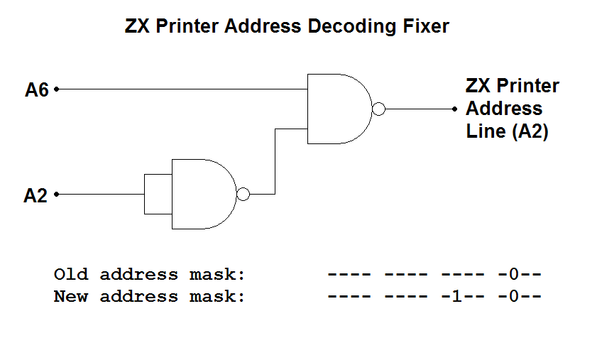
Note: Because of incomplete decoding, both by Sinclair and third-party add-on manufacturers, there are no free I/O ports on the Spectrum. Port xx3B was chosen because it clashes with only one item of hardware - the ZX Printer.
ZX Printer Fix
The following modification to the ZX Printer circuit prevents it being triggered by access to port xx3B.
Software
A rapidly growing collection of software is available including a palette editor, palette files to re-colour existing games, a 6-bit RGB colour extension to CP/M plus, a slideshow of converted Commodore 64 hi-res pictures, and brand new games, all of which can be found at [http://sites.google.com/site/ulaplus/home].
The palette editor enables you to create a palette for use with existing software without needing to rewrite the software. You can save the palette and load it before loading the original software as normal. In this way all existing software can be re-coloured without any programming knowledge required.
Limitations
Although in theory 64 colours can be displayed at once, in practice this is usually not possible except when displaying colour bars, because the four CLUTs are mutually exclusive; it is not possible to mix colours from two CLUTs in the same cell.
Emulation
The 64 colour mode lookup table is organized as 4 palettes of 16 colours.
Bits 7 and 6 of each Spectrum attribute byte (normally used for FLASH and BRIGHT) will be used as an index value (0-3) to select one of the four colour palettes.
Each colour palette has 16 entries (8 for INK, 8 for PAPER). Bits 0 to 2 (INK) and 3 to 5 (PAPER) of the attribute byte will be used as indexes to retrieve colour data from the selected palette.
With the standard Spectrum display, the BORDER colour is the same as the PAPER colour in the first CLUT. For example BORDER 0 would set the border to the same colour as PAPER 0 (with the BRIGHT and FLASH bits not set).
The complete index can be calculated as ink_colour = (FLASH * 2 + BRIGHT) * 16 + INK paper_colour = (FLASH * 2 + BRIGHT) * 16 + PAPER + 8 When scaling 3-bits of colour data to 8-bits for emulators that operate in high colour mode the following conversion should be used: 76543210
hmlhmlml where h is the high bit, m is the middle bit, and l is the low bit of the original 3-bit value.
Extension to the SZX Format
ZXSTPALETTE
The state of the ULA registers found in the 64 colour replacement ULA. This block may be present for any machine. // Palette Block flags #define ZXSTPALETTE_DISABLED 0
#define ZXSTPALETTE_ENABLED 1
// Palette Block. Contains the palette register values typedef struct _tagZXSTPALETTEBLOCK {
  ZXSTBLOCK blk;
  BYTE chFlags;
  BYTE chCurrentRegister;
  BYTE chPaletteRegs[64];
} ZXSTPALETTEBLOCK, *LPZXSTPALETTEBLOCK;
Members
blk
The block header. The block id is ZXSTBID_PALETTE ('P', 'L', 'T', 'T').
chFlags
A flags that indicates if the palette is enabled or if the normal display mode is in use. This can be one of:
| Flag | Meaning |
| ZXSTPALETTE_DISABLED | Normal palette mode with BRIGHT and FLASH |
| ZXSTPALETTE_ENABLED | 64 colour palette mode |
chCurrentRegister
The currently selected palette register (0-63).
chPaletteRegs
The current values of the palette registers.
Extension to the SCR Format
A 6912 byte .SCR file contains a standard Spectrum screen.
A 6976 byte .SCR file contains a standard Spectrum screen followed by 64 colour registers.
A 12288 byte .SCR file contains a Timex hi-colour screen.
A 12352 byte .SCR file contains a Timex hi-colour screen followed by 64 colour registers.
A 12289 byte .SCR file contains a Timex hi-res screen.
A 12353 byte .SCR file contains a Timex hi-res screen followed by the hi-res colour information that was dumped from port 255, followed by 64 colour registers.
Palette File Format
The palette format doubles as the BASIC patch loader. This enables you to edit patches produced by other people.
; 64 colour palette file format (internal) - version 1.0
; copyright (c) 2009 Andrew Owen
;
; The palette file is stored as a BASIC program with embedded machine code
header:
db 0x00 ; program file
db 0x14, 0x01, "64colour" ; file name
dw 0x0097 ; data length
dw 0x0000 ; autostart line
dw 0x0097 ; program length
basic:
; 0 RANDOMIZE USR ((PEEK VAL "2
; 3635"+VAL "256"*PEEK VAL "23636"
; )+VAL "48"): LOAD "": REM
db 0x00, 0x00, 0x93, 0x00, 0xf9, 0xc0, 0x28, 0x28
db 0xbe, 0xb0, 0x22, 0x32, 0x33, 0x36, 0x33, 0x35
db 0x22, 0x2b, 0xb0, 0x22, 0x32, 0x35, 0x36, 0x22
db 0x2a, 0xbe, 0xb0, 0x22, 0x32, 0x33, 0x36, 0x33
db 0x36, 0x22, 0x29, 0x2b, 0xb0, 0x22, 0x34, 0x38
db 0x22, 0x29, 0x3a, 0xef, 0x22, 0x22, 0x3a, 0xea
start:
di ; disable interrupts
ld hl, 38 ; HL = length of code
add hl, bc ; BC = entry point (start) from BASIC
ld bc, 0xbf3b ; register select
ld a, 64 ; mode group
out (c), a ;
ld a, 1 ;
ld b, 0xff ; choose register port
out (c), a ; turn palette mode on
xor a ; first register
setreg:
ld b, 0xbf ; choose register port
out (c), a ; select register
ex af, af' ; save current register select
ld a, (hl) ; get data
ld b, 0xff ; choose data port
out (c), a ; set it
ex af, af' ; restore current register
inc hl ; advance pointer
inc a ; increase register
cp 64 ; are we nearly there yet?
jr nz, setreg ; repeat until all 64 have been done
ei ; enable interrupts
ret ; return
; this is where the actual data is stored. The following is an example palette.
registers:
db 0x00, 0x02, 0x18, 0x1b, 0xc0, 0xc3, 0xd8, 0xdb ; INK
db 0x00, 0x02, 0x18, 0x1b, 0xc0, 0xc3, 0xd8, 0xdb ; PAPER
db 0x00, 0x03, 0x1c, 0x1f, 0xe0, 0xe3, 0xfc, 0xff ; +BRIGHT
db 0x00, 0x03, 0x1c, 0x1f, 0xe0, 0xe3, 0xfc, 0xff ;
db 0xdb, 0xd8, 0xc3, 0xc0, 0x1b, 0x18, 0x02, 0x00 ; +FLASH
db 0xdb, 0xd8, 0xc3, 0xc0, 0x1b, 0x18, 0x02, 0x00 ;
db 0xff, 0xfc, 0xe3, 0xe0, 0x1f, 0x1c, 0x03, 0x00 ; +BRIGHT/
db 0xff, 0xfc, 0xe3, 0xe0, 0x1f, 0x1c, 0x03, 0x00 ; +FLASH
terminating_byte:
db 0x0d